
BackgroundConvert a Handheld GMRS Radio into a Mobile Unit
Nelson Sievers
GMRS FCC Lic. WPXM894
In recent years, the FCC has changed the licensing requirements for operating in the General Mobile Radio Service band, allowing private citizens access to these frequencies. This service is in the UHF radio spectrum and has some frequencies which coexist with the family radio service, (FRS). By now, most people are familiar with the license-free FRS radios that have 14 allocated frequencies. But unlike FRS radios, GMRS sets require an FCC license. Also, FRS sets cannot operate using more than 0.5 Watts of power while GMRS sets can operate with up to 50 Watts. FRS sets are also FCC restricted to using small built-in antennas. The set that I modified has 7 shared FRS channels, 7 stand-alone FRS channels, and 8 stand-alone GMRS channels. The unit can transmit using 3 Watts of power on all but the 7 stand-alone FRS channels, where it uses only the legal 0.5 Watts. Be aware that it illegal to use an external antenna on these 7 channels. While on the subject of legality, I strongly support the use of licensing. GMRS radios are usually displayed in stores alongside of FRS radios, leading consumers to believe that they are also license-free. The licensing information is often hidden or in small print. If this service is to remain viable, it's necessary to enforce licensing and FCC rules. Anyone who remembers the CB craze of the 1970's knows how chaotic and useless that form of communications became.
Here is a breakdown of the GMRS and FRS channel allocations. Note the overlapping of services for the first 7 frequencies.
 Fig 1 Frequency Table
The Radio
For this project I used a Cobra model PR4000WX, which I've found to be one of the better units in a market flooded by mostly second rate garbage. The unit provides 3 power levels, the highest being 3 Watts, (except on the FRS-only frequencies). It has 7 NOAA weather channels and can be programmed for weather alerts. It also provides CTCSS, (PL) tones for private calling. In addition, it can be configured for VOX transmitting, roger beep, channel scanning, calling ring tones to name a few. It even has a digital compass, although this feature will not function well when mounted in your vehicle.
Adding a BNC Antenna Connector
The first and foremost step in converting the unit is to add a connector for an external antenna. A good antenna with the right placement can improve a radio's performance many fold. This fact cannot be stressed enough. Two vehicles can converse clearly while many miles apart using external mobile antennas. A base station with good antenna height can amaze you with it's range.
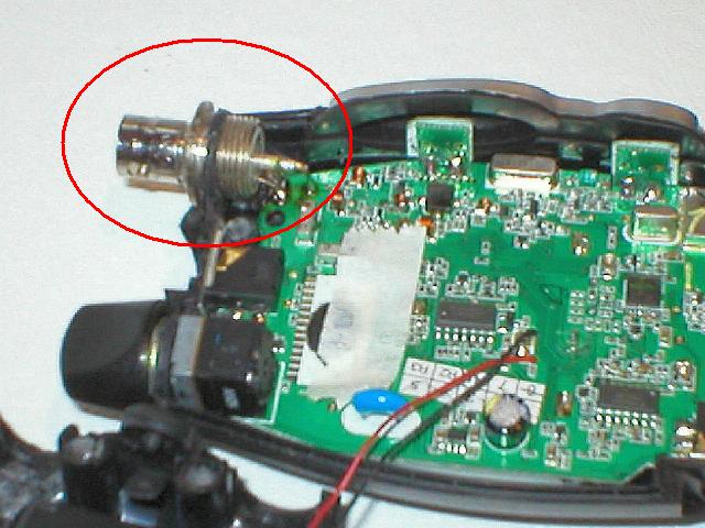
To begin, remove the rear battery cover and remove the 4 phillips screws, then the 2 remaining screws near the top. Carefully separate the case. The battery cover retainer will probably fall off at this point, but don't be dismayed, as it's simple to reinstall later on. Just be careful not to lose the metal pin that acts as a hinge. Next, remove the antenna cover. The actual antenna is a coiled wire that is soldered to the PCB. There is some foam material inside of the cover to stabilize the antenna, but the cover pulls off quite easily. The next step is to solder in the BNC connector. You will first need to solder a short wire lead to the center connector. I used a gold plated lead salvaged from a wire-wrap IC socket I found in my junk box, but you can use whatever is handy. After completing this step, lay the BNC socket so that the ground connection lies on the PCB. There is a land connected to ground right at this spot. If you're unsure, test continuity to the negative battery connector. Scrape of any laminate coating and apply some flux on both the connector and the PCB land and solder with a 30-40 Watt iron. Then insert the center lead where you removed the internal antenna using a little flux again. You may need to clean out the hole first with some solder braid. When finished, you should have a mechanical bond as well as electrical. Reassemble the case, (unless you want to install an external power connector described later). Make sure that the grommet is aligned properly and the push-to-talk bar is in place. Install the screws, but before they're completely tightened, reinstall the battery cover retainer. When the screws are tightened all the way, the hinge pin will become secured.
Fig 2 BNC Installation
(The BNC connector pictured was manufactured by Kings Electronics, Inc Tuckahoe, NY 10707)
Adding an External Power Jack
 Fig 3 Coaxial power jack on back cover
Installing the Jack
This part is pretty straight forward. I used a coaxial type jack/plug combination from Radio Shack, but if you have something lying around that fits the bill, by all means use it. Drill the mounting holes, mount the jack and solder a pair of wires between it and the battery terminals. Pay attention to the polarity. It doesn't matter if you make the center positive or negative as long as it's consistent with the voltage regulator and the battery terminals. In fact, it's a good idea to hold off on soldering to the battery terminals until you test for proper polarity and voltage with a meter while applying power.
The Regulator
The regulator consists of a zener diode, a high current pass transistor and a single resistor. The transistor should be mounted on a heat sink using appropriate mounting hardware. You'll need a cigarette lighter adaptor, preferably one with a built-in fuse for the input, and the coaxial plug described in the previous step for the output. I housed mine in a salvaged metal case that I found in my junk box. Component placement is not critical.
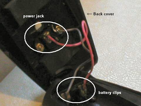 Fig 4 Power wiring

Fig 5 Regulator Schematic
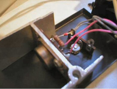 Fig 6 Regulator wiring
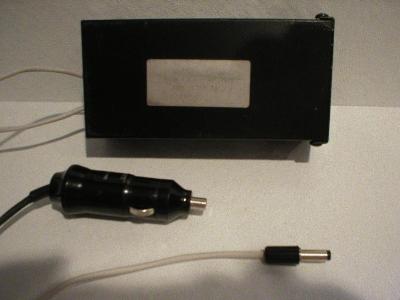 Fig 7 Completed voltage regulator
A Mobile Antenna
Although antenna construction and design is beyond the scope of this article, I'll present the antenna that I used for this project. This is simply a surplus mobile cell phone magnet-mount antenna that I modified for this band. This is a quarter wave design that is cut for the center of the GMRS band. You could cut it to optimize a particular channel if you desire. This particular mount allows you retract the rod slightly to fine tune it. The best way to adjust an antenna is with the aid of an SWR meter. The coax is of the type RG58 terminated with a male BNC connector.
The formula for a quarter wave vertical antenna is:
L = 234/f (MHz)
Simply divide the desired frequency by 234 to derive the length in inches.
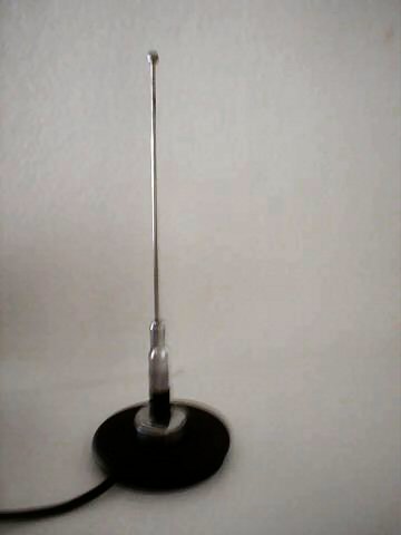 Fig 8 Mobile whip antenna
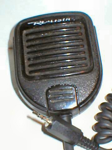
You're going to need a speaker mike, or at least a hand-held mike for your mobile rig. The one at the left is a converted Radio Shack model. It originally had a dual plug used for 2 meter amateur handhelds. The Cobra PR4000, and many other modern radios use a single stereo mini-plug as pictured in Fig 11. You can obtain these through Mouser Electronics and other suppliers. Note: When the plug is engaged, the internal speaker is disabled.
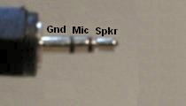 Fig 9
Fig 9
If you don't care for the sound from the miniature speaker in a speaker mike, you could use a satellite speaker or amplified speaker by splitting out the speaker lead.
Any electret microphone element should work for transmitting, but don't include the usual resistor. Apparently, Cobra provides one internally. For the pictured speaker mike, I had to bypass a 2.2k resistor for proper operation.
 Fig
10 Speaker mike
Fig
10 Speaker mike
Mounting the Radio
To mount my radio I used an old cell phone mount. The radio easily snaps into it's belt clip which is bolted to the top of the mount. The mount is held by screws to a wooden cylinder that fits into the cup holder in my vehicle's console. Some duct tape was added to make a snug fit
As you can see, much of this project was improvised from odds and ends, but to me, that is half the fun of it! To customize this for your own purposes, you will need to brainstorm for yourself. Use your imagination while looking at ordinary items around you, and you'd be surprised how many things can be adapted for purposes other than what they're designed for.
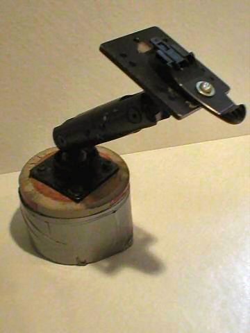 Fig 11
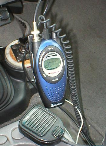 Fig 12 Completed conversion and installation
Going Further
What else can you do once you've installed an external antenna connector? How about building a pair of highly directional Yagi antennas? You can get a pair of radios communicating with crystal clarity that are miles away by pointing the Yagis at each other. Plans can be found on the Internet or your public library. How about a linear amplifier? Modern UHF power transistors are cheap and have excellent operating characteristics. Building a 25 Watt linear would not be difficult, and plans aren't hard to obtain. An amateur 440 MHz amplifier could be redesigned fairly easily to accommodate 460MHz. I didn't mention this earlier, but there are additional frequencies available for creating repeater pairs. This could get pricey, but if you can get a hold of some surplus UHF equipment, you could setup a communications repeater. The cost could be defrayed if you form a club or co-op amongst friends and neighbors. Then you could rent a tower location to house your repeater with enough height to cover your entire town. The possibilities are only limited by your imagination.
Electronic components, GMRS radios, soldering irons, printed circuit boards, switches, connectors, resistors, IC, integrated circuits, schematics, circuits